LPG Cylinder Shell Drawing Machine
Model NO.: Longterm Machinery
Production Scope: Parts Production Line
Machine Name: Deep Drawing Hydraulic Press Machine
Cylinder Size: 6kg, 12kg, 25kg, 48kg, or Customized
Cylinder Thickness: 2.5~4mm or Customized
Cylinder Diameter: 250~800mm or Customized
Pressure Range: 200t-400t
Drawing Slide Speed: 100mm/S
Presser: Hydraulic
Capacity: 4PCS/Min
Controller: PLC
Customized: Acceptable
Trademark: LONGTERM
Transport Package: Standard Seaworthy Package
Origin: China
HS Code: 844790900
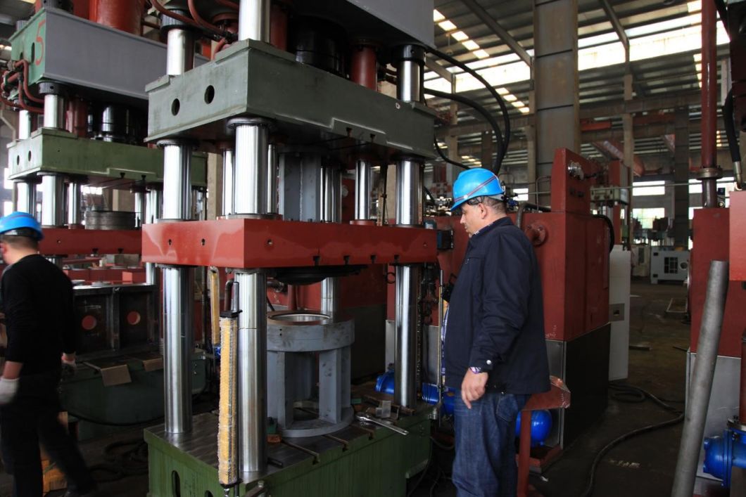
LPG Cylinder Shell Drawing Machine
A. Product Description
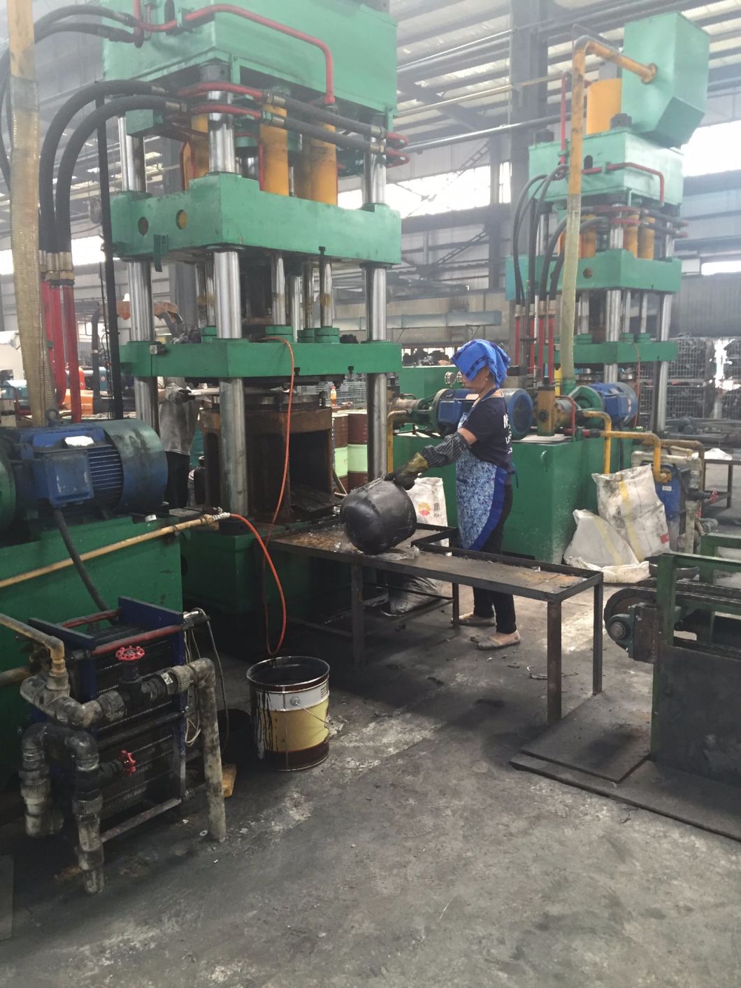
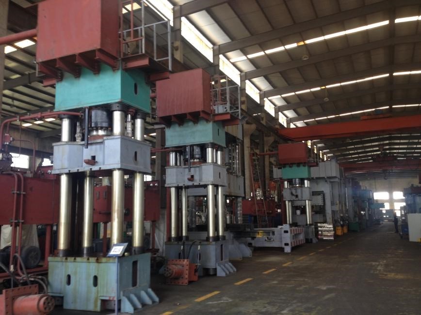
This machine is a four-column double-action hydraulic press, suitable for the stretching and drawing of metal sheets. It features an independent power system and electrical control, allowing centralized button operation. The PLC control system enables inching and semi-automatic functions. Both working pressure and stroke distance can be adjusted according to technological requirements.
The production line is applicable for LPG Gas cylinder/tank of sizes: 6KG /12KG /15KG /50KG or customized. Each machine comes with a one-year warranty, and our engineers can provide overseas service.
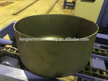
B. Production Process
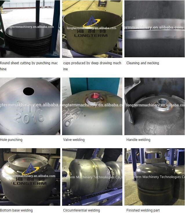
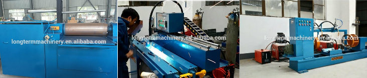
Rolling Machine                          Longitudinal Welding Machine                      Double Head Circumferential Welding Machine
Complete Machines of the LPG Cylinder Production Line:Â
| No. | Description | Size&Specis | Unit |
| I | Main Equipment | Â | Â |
| 1 | Hydraulic Press | 500T | set |
| 2 | De-colier and punching machine for small round sheet cutting from big sheet (material preparing for shell) | XL-2 | set |
| 3 | Material cutting mould on hydraulic press | Â | set |
| 4 | 63ton hydraulic logo stamping machine | 63T | set |
| 5 | Shell drawing machine | 200/300 | set |
| 6 | Shell forming mould | LS-2 | set |
| 7 | Automatic trimming machine | QK-4 | set |
| 8 | End dish necking machine | SK-3 | set |
| 9 | Cleaning machine | QL-5 | set |
| 10 | Hole punching machine | CK-3 | set |
| 11 | Valve Seat Welding Machine | HP-2 | set |
| 12 | Shroud welding machine | HZ-1 | set |
| 13 | Bottom base welding machine | DZ-1 | set |
| 14 | Assembling Machine | ZH-1 | set |
| 15 | Option NO.1:Circumferential Seam welding machine | HJ-3 | set |
| Option NO.2:Circumferential seam welding machine | Single head MAG | set | |
| 16 | Annealing furnace with burner | TW-1 | set |
| 17 | Hydrostatic Testing Machine | SY-6 | set |
| 18 | Shot blasting machine | QYP15 | set |
| 19 | Spraying line | JH-2 | set |
| 20 | Valve mounting machine | JF-2 | set |
| 21 | Air Leakage Testing Machine | Cm-2 | set |
| 22 | Printing machine | ZS-2 | set |
| 23 | Roller conveyor line | Â | m |
| 24 | Curve Convoyer | Â | m |
| 25 | Conveyor line power | Â | set |
| 26 | Motorized testing pump | Â | set |
| 27 | Cylinder drying machine | Â | set |
| II | Equipment For Accessories Manufacturing Equipment | Â | Â |
| 28 | Punching machine/power press | 25T | set |
| 29 | Punching machine/power press | 63T | set |
| 30 | Punching machine/power press | 100T | set |
| 31 | Bottom base hydraulic forming machine | Â | set |
| 32 | Shroud upper RÂ hydraulic forming machine | Â | set |
| 33 | shearing machine | 4mm*1.5m | set |
| 34 | Shearing machine | 4mm*2.5m | set |
| 35 | Printing machine | GZ-2 | set |
| 36 | Coding machine | BM-1 | set |
| 37 | Shroud rolling machine | Â | set |
| 38 | Bottom base rolling machine | Â | set |
| 39 | Shroud mould | Â | set |
| 40 | Bottom base mould | DM-2 | set |
| 41 | Bottonm base welding machine | Â | set |
| III | Auxiliary Equipment | Â | Â |
| 42 | Air compressor (screw) | 10/0.8 | set |
| 43 | Air compressor (piston) | 2.0/3.0 | set |
| 44 | Air storage tank | 1m3/3Mpa | set |
| 45 | Air storage tank | 2m3/1Mpa | set |
| IV | Testing Equipment | Â | Â |
| 46 | X-ray detecting equipment | 2505C | set |
| 47 | Mechanical property testing equipment | WES-600B | set |
| 48 | Burst pressure testing equipment | Â | set |
| 49 | Ultrasonic wall thickness testing equipment | Â | set |
- Overview of Machine Structure and Performance
1.1 Machine Body:
The body consists of an upper beam, stretching slider, blankholder slider, operating platform, and uprights. The upper beam and operating platform form a closed frame through the uprights and nuts. The body has good rigidity and precision retention. The stretching and blankholder sliders move up and down along the uprights; the guide sleeve of the upright is a composite copper sleeve to increase surface load capacity and reduce friction. The upright is made of 45# steel with surface quenching treatment.
The upper beam, stretching slider, blankholder slider, and operating platform are all welded steel structures. After welding and high-temperature annealing, machining is completed. Polishing ensures no weld slag or scars in the weld joints, ensuring a flat and aesthetically pleasing appearance, high accuracy, and good rigidity.
1.2 Oil Cylinder:
The stretching oil cylinder uses a piston cylinder installed inside the upper beam. The cylinder body is fixed to the upper beam via flanges, and the piston rod connects to the stretching slider via a connecting flange.
The blankholder oil cylinder uses six piston cylinders installed around the stretching oil cylinder. The cylinder body is fixed to the upper beam with flanges, and the piston rod connects to the blankholder slider via a connecting flange.
The cylinder body is made of high-quality forged steel with uniform material quality. Surface quenching is applied to all piston rods. The oil cylinders undergo a high-voltage insulation test (1.1 times).
The oil cylinders are sealed with imported sealing elements to ensure reliable sealing, no leakage, and easy maintenance.
1.3 T-shaped Slot:
There are T-shaped slots on the operating platform, stretching slider, and blankholder slider. The size of the T-shaped slot is standard for convenient mold installation.
Â
- Electrical Control System:
2.1 Power Part: Controls the main power and start/stop/protect switches for all motors. High-power motors use a tri-star depressurized sequential startup, which reduces impact on the power grid and has strong anti-jamming capability.
2.2 Control Part: Includes the main control console and mobile button station. The main control console can control and operate all actions of the machine. The electrical box has high leakproofness and effectively prevents dust intrusion.
The main control console is equipped with operating buttons and function switches for all actions of the host machine, as well as start/stop, alarm, supervision, and monitor display, allowing real-time control of the hydraulic press.
The mobile button station, used for semi-automatic operation, includes two-hand pressing buttons and emergency stop buttons.
Â
- Hydraulic Part:
3.1 The hydraulic system uses an advanced plug-in valve integrated system. The valve is characterized by high flow, anti-pollution, flexible control, reliable performance, and easy maintenance.
3.2 The working pressure of the hydraulic system is 25MPa. A high-pressure constant power variable oil pump is used as the main oil pump. The stretching and blankholder cylinders share one pump set and are distributed reasonably based on technological needs. The hydraulic system is equipped with an overload protection device.
3.3 The oil tank adopts a welded steel structure, equipped with an oil level indicator and air filter. During installation, the oil tank undergoes pickling, passivation, and rust-proof treatment. Additionally, the oil tank is equipped with an oil filter unit, with filter precision ensuring the cleanliness of the working oil and capable of alarming for filter blockage accidents.
3.4 The hydraulic pipeline system must be sealed and reliable. Flange connections are preferred. Pipelines should be arranged neatly, with seismic pipe clamps and vibration-resistant pressure gauges. After phosphating, the pipelines are coated with rust-proof and oil-proof paint. Exposing oil pipes in front of the host machine is not allowed.
3.5 Description of Prefill Valve: The prefill valve is mainly used for oil absorption and discharge by the main cylinder. When the slider moves downward rapidly, the negative pressure formed in the upper chamber of the main cylinder opens the prefill valve, allowing abundant oil from the oil tank to fill the oil cylinder. When the slider stops moving, the prefill valve closes under spring force;
during the return stroke of the slider, the control oil opens the pressure relief valve for pressure relief, then the valve core opens to allow oil to be discharged toward the oil tank.
3.6 To effectively control hydraulic system leakage, the following measures are taken:
3.6.1 The faying surfaces (valves, valve blocks, flanges, pipe connections) are sealed with high-quality seal rings. All parts of the system are reliably sealed to avoid air inclusion and effectively prevent oil leakage from shell attachments and welding parts.
3.6.2 Pipes are arranged neatly with distinct colors to differentiate high-pressure and low-pressure pipes. Flange connections are preferred. Sufficient quakeproof and vibration-isolating pipe clamps are provided. Maximize the use of integrated connections to reduce seepage points.
3.7 Regarding the cooling system, a plate-type water cooler is adopted. It is stipulated that the allowable normal working oil temperature of the press shall be greater than 10ºC and less than 60ºC. The demander must provide their own water source (the temperature of cooling water shall not exceed 25ºC).
Â
4. Operating Mode of Press
4.1 The press is equipped with inching and semi-automatic (two-hand single cycle) operations; these operations can be switched using a change-over switch and controlled centrally with buttons.
(1) Inching: A corresponding action is initiated by pressing a certain working button and stopped by releasing the button; inching is mainly used for machine adjustment. This action cannot be fast.
(2) Semi-Automatic (Two-Hand Single Cycle) Operation: Press the two-hand downward button, and the press will continuously complete a specified single cycle process.
4.2 The holding time can be set using a time relay.
Â
5. Safety Protection Measures for Device
5.1 Static and Emergency Stop Buttons: In case of any unusual conditions, pressing the "static" button will completely stop the press's work; pressing the "emergency stop" button will stop both the press and the motor.
5.2 Overload Protection: The hydraulic system must include a hydraulic relief valve to prevent damage due to overload operation.
5.3 There are travel switches at the extreme positions of the slider's upstroke and downstroke.
5.4 There is a hydraulic supporting insurance loop in the lower chamber of the main cylinder.
5.5 Buttons must be operated with both hands.
5.6 There is a group of photoelectric safety devices on the front side of the press, with a protection height of 600mm.
Â
6. Equipment Working Condition:
6.1 Voltage: Three-phase 380 V (±10%), 50 Hz
6.2 Working Temperature: -5~40°C, Humidity: Maximum 80%
Equipment Inspection Standard
1. Precision: According to GB/T 9166-2009 Precision Four-Column Type Hydraulic Press
2. Design and manufacture should follow related standard requirements of hydraulic machines:
JB/T 3818-1999 Hydraulic Machines Technical Specification
GB5226.1-2002 Mechanical Safety - Mechanical Electric Device - Part 1: General Technical Specification
JB/T 8609-1997 Metal Forming Machine Welding Technical Specification
JB/T 3623-1984 Metal Forming Machine Noise Testing
Â
C. F&Q:
We are professional manufacturers of LPG tank production lines. To provide you with the correct machinery, we need the following information:
Q: What size of LNG cylinder can your machine produce?
A: 15kgs and 50kgs LNG cylinders and other sizes as per customer requirements.
Q: Can you design machines according to LNG cylinder technical drawings?
A: Yes, please send us your technical drawings.
Q: What are the benefits of choosing your machines?
A: Our machines are strong and reliable for long-term industrial manufacturing.
To enable us to give you the correct proposal for the right machines, please provide the following details:
1. Can you send me the technical drawing of the cylinders you want to make?
2. What size of cylinder do you want to produce? (15kg, 50kg)
3. What kind of gas will be used inside the cylinder? Nitrogen, Oxygen, etc.
4. What temperature?
5. What diameter and thickness of the cylinder do you want to make?
6. What length and material of the cylinder do you want to make, stainless steel or carbon steel?
7. Are you new to this area or do you already have some machines in the workshop?
8. What capacity do you require, i.e., how many pieces and sizes do you want to make per day?
Jet Mill,Energy Saving Jet Mill,Glass Beads Classifying Jet Mill,Pesticide Industry Specific Jet Mill
Mianyang Liuneng Powder Equipment Co., Ltd , https://www.lnpepowder.com