Analysis and Improvement of Temperature Characteristics of Thermoelectric Thermoelectric Element
Analysis and Improvement of Temperature Characteristics of Thermoelectric Thermoelectric Element
Zhao Hanjie (Liaoning Electric Power Research Institute, Shenyang 110006)
Abstract : The dynamic characteristics of the temperature measurement process of thermoelectric thermoelements is determined by its own structure, processing technology and installation method. This paper proposes methods to improve the dynamic characteristics of thermoelectric elements for temperature measurement from aspects of design, manufacture and use. Professionals in the design, manufacturing, and use departments.
Keywords: temperature thermoelectric element dynamic characteristics improvement
Thermoelectric thermoelements used in production process monitoring and control include thermocouples and thermal resistors. The structure of the thermoelectric elements varies depending on the parameters and states of the measured medium and the mounting method. Temperature thermoelectric elements commonly used in power systems include thermocouples (thermal resistance) for measuring fluid medium temperature with protective tubes; surface-type thermocouples (thermoresistors) for measuring metal body temperature, pressure vessels, and pipelines; Thousands of thermocouples (thermal resistance) for rotary machine bearings, bearings, and thrust pads; embedded thermocouples (thermal resistance) for measuring the temperature of motor core coils and thermocouples (thermal resistance) for measuring air temperature. The thermoelectric elements, regardless of their structure or how the temperature measurement principle is different, change the temperature of the sensitive part with the temperature of the measured medium. Therefore, the temperature-measurement thermoelectric element must perform heat exchange with the measured medium during temperature measurement. The response speeds of temperature measurement thermoelectric elements with different structures and different uses have great differences due to the speed of heat exchange and the magnitude of thermal inertia. Therefore, it is necessary to carry out the dynamic characteristics of temperature measurement thermoelectric elements. Research to guide the component processing technology and structural improvement, guide the design of the monitoring system, component selection, sample installation and commissioning, to improve the reliability of the production process, economic, and improve product quality.
1 Temperature characteristics of thermoelectric elements:
1.1 Dynamic Characteristics of Thermocouples (Thermistors) Without Protection Tubes
Thermocouples without a protective tube (thermal resistance) are often used for surface temperature and buried temperature measurements, such as metal wall temperatures, bearing temperatures, motor core coil temperatures, etc., and are rarely used directly in other applications such as flowing media. When a thermocouple (thermal resistance) is used for temperature measurement, the temperature change of the thermocouple (eg, temperature rise) is due to the heat flowing between the measured medium (heat source) and the thermocouple element, which belongs to the heating (cooling) process of an object. . When the heat source temperature is θ1, the temperature θ2 of the object changes due to the change of θ1. Let X = θ1 and Y = θ2 be the model for heating (cooling) the object as shown in Fig. 1.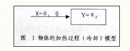 Surface temperature measurement and buried temperature measurement are mainly based on heat conduction. The heat transfer rate, ie, heat flow rate Q, can be expressed by Fourier's law as follows:
Q=λΔt•F/δ=λ(θ1-θ2)F/δ (1)
In the formula: Q, λ, δ, F, Δt, θ1, θ2 are heat flow (heat transferred per unit time), thermal conductivity, thickness of heat-conducting layer, heat-conducting area, temperature difference, and sensitive area of ​​measured medium and heat element. temperature. From formula (1), we can see that the thermal conductivity is proportional to the thermal conductivity, the thermal conductivity area and the temperature difference, and is inversely proportional to the thickness of the thermal layer. According to formula (1), people choose the insulating material with high thermal conductivity to manufacture the temperature measuring element and try to increase the temperature The contact area between the component and the measured medium, and the thickness of the insulating layer as much as possible to improve the response speed of the temperature measurement process.
Equation (1) is similar to the current conduction formula in the wire:
I=λU•S/I=λ(V1-V2) • S/I=gΔV=U/R...(2)
In the formula, I is the current, λ is the conductivity, U is the voltage, S is the cross-section of the wire, I is the length of the wire, and V1 and V2 are the potentials at both ends of the wire. (2) where λ•S/I is the conductance g of the wire, and its reciprocal is resistance R, which is an analogy. If we make λ•F/δ=gR in (1), gR is the thermal conductivity. , then 1/gR = RR is the thermal resistance during heat transfer. Therefore, (1) can be written as:
Q=λΔt•F/δ=gRΔt=Δt/RR...(3)
The actual heat transfer in the temperature measurement process is often not a simple heat conduction, for example, the components often come into point contact with the solid surface, the heat transfer layer often has an air gap, etc. Therefore, the temperature measurement process is always accompanied by heat radiation and convection. Exothermal.
In fact, most of thermoelectric thermoelements have the same three heat transfer methods during temperature measurement. Only the surface temperature measurement and buried temperature measurement process is based on heat conduction, while heat radiation and convection heat transfer Less; while in the process of fluid temperature measurement, there is more convection heat, and both thermal radiation and heat conduction exist.
In order to facilitate the study of the dynamic characteristics of the thermoelectric element for temperature measurement, we convert all three heat transfer methods to the heat conduction method and express the basic formula of heat transfer as follows:
Q=KFΔt...(4)
In the formula, k is the heat transfer coefficient, and F is the area of ​​the two heat exchange sections. The product of the two is the thermal conductivity gR in the formula (3), which is called the equivalent thermal conductivity. Let RR=1/gR be the pass Equivalent thermal resistance in thermal processes. Therefore, (4) can be written as:
Q=gRΔt=Δt/RR...(5)
This is the same as the expression of the current calculation formula in the conductor.
Assuming that the thermal capacity of the heat-sensitive area of ​​the device is CR, the temperature-rise characteristics of the device's heat-sensitive area during the temperature measurement process is the same as the charge and discharge process of the capacitor. When the input θ1 is a unit step function, the output will be Increase by exponential curve, ie:
Θ2=θ1(1-et/T)......(6)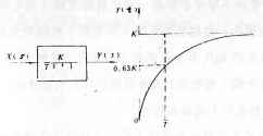
Its flying characteristic curve is shown in Figure 2
It can be seen from Fig. 2 that the temperature measurement process of the surface type and embedded components belongs to the inertia link. In the figure, the time T is the time when the output θ2 rises to 0.632 times the stable output value K, which represents the time The magnitude of inertia, called the inertia time constant, is equal to the product of equivalent thermal resistance and heat capacity, ie T = RRCR. The transfer function of this link is:
G1(S) = K/(TS+1)......(7)
From Equation (7) and T=RRCR, it can be seen that the product of the equivalent thermal resistance of the component temperature measurement process and the thermal capacity (mass size) of the sensitive component of the component determines the response speed during temperature measurement.
1.2 Dynamic Characteristics of Armored Thermocouples (Thermistors)
The temperature measurement process (excluding axial heat transfer) of a general sheathed thermocouple (thermal resistance) without a protective tube can proceed from the measured medium to the end of the heating element body (stage 1) and from the end of the body. The element end (thermocouple hot junction or thermal resistance element) (link 2) is divided into two parts, and the dynamic characteristics of the two parts of the temperature measurement process are first order inertia links. Let G1(S) and G2(S) be the transfer functions of link 1 and link 2, respectively. K1 and K2 are the gains of the two links, and T1=R1C1 and T2=R2C2 are the inertia time constants of the two links, respectively. The dynamic mathematical models of the two links are:
G1(S) = K1/(T1S+1) (8) G2(S) = K2/(T2S+1) (9)
In the process, heat passes through the link 1 and link 2 to the sensitive area of ​​the thermal element in sequence from the measured medium, so the two links are in series. The transfer function G(S) of the whole process is the product of the two links transfer function, ie:
G(S)=G1(S)•G2(S)=K1•K2/(T1S+1)(T2S+1)=K/(T1S+1)(T2S+1)......(10)
Where K is the gain of the whole system, according to the output Y is the temperature, its value is 1°C/°C=1, and the output is calculated as the thermoelectric potential, and the value is according to the different thermocouple's index number according to each section of its thermoelectric value curve. Calculation, the dimension is mV/°C. From the formula (10), it can be seen that the temperature measurement process of a general sheathed thermocouple (thermal resistance) without a protective tube has a second-order inertial characteristic. However, because the outer diameter of the general sheathed thermocouple (thermal resistance) and the thermal element are small, and the insulating layer outside the thermal element is a dense MgO with high thermal conductivity, its T1 = R1C1 and T2 = R2C2 are both Very small, so armored thermocouples (thermal resistance) have a very fast dynamic response.
1.3 Dynamic Characteristics of Assembled Thermocouples (Thermistors)
The dynamic characteristics of an assembled thermocouple (thermal resistance) with a protective tube are similar to those of a general sheathed thermocouple (thermal resistance) without a protective tube, and can be measured from the medium to the end of the protective tube (stage 1). ) and from the end of the protective tube to the end of the thermal element (thermocouple hot junction or thermal resistance element) (link 2) is divided into two links, it is also a second-order inertial system. In the first step, heat conduction, convection and radiation exist at the same time. Since the protection tube has a large size (C1 is large), it has a large T1 value; the second part of the heat transfer medium is not MgO but mainly air. The gap has a large thermal resistance and therefore has a large T2 value; this results in a very slow dynamic response speed of the assembled thermocouple (thermal resistance). Figure 3 shows the fly-through characteristics of a preassembled thermocouple with a shroud pipe that rapidly transfers from an ice bath to a boiling water bath. It can be seen from the figure that the dynamic response speed of an assembled thermocouple is indeed very slow.
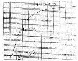
Fig. 3 Flying characteristic curve of an assembled thermocouple with protective tube
1.4 Dynamic characteristics of a full armored thermocouple (thermal resistance) with protective tube
The temperature measurement process (excluding axial heat transfer) of the full armored thermocouple (thermal resistance) with protective tube can be from the measured medium to the end of the protective tube (stage 1) and from the end of the protective tube to the end of the body (Section 2) and divided into three links from the end of the carcass to the sensitive area of ​​the thermal element (Link 3). The dynamic characteristics of the temperature measurement process of these three links are the first-order inertial system. Let G1(S), G2(S), and G3(S) be the transfer functions of link 1, link 2, and link 3, respectively. K1, K2, and K3 are the gains of the three links, respectively. T1 = R1C1, T2 = R2C2 And T3 = R3C3 are the inertia time constants of three links respectively, then the dynamic mathematics model of three links are:
G1(S)=K1/(T1S+1)......(11)G2(S)=K2/(T2S+1)......(12)G3(S)=K3/(T3S+1)......(13 )
In the heat transfer process, there are three kinds of heat transfer methods in the link 1, but the convection heat transfer component is larger; the link 2 is mainly based on conduction and radiation; and the link 3 is mainly heat transfer method, where T1, T2 T3, respectively, are the three inertial time constants, which are determined by the product of the respective heat transfer resistance and the heat capacity of the respective heat transfer target object.
The overall mathematical model of the temperature measurement process of a sheathed thermocouple (thermal resistance) with protective tube is: G(S) = K1/(T1S+1)•K2/(T2S+1)•K3/(T3S+1)= K/(T1S+1)•(T2S+1)•(T3S+1)......(14)
Visible, it is a third-order link. Although the temperature measurement system belongs to the third-order inertial system, due to the use of armored components and the fistula tube and the protection tube can be in direct contact, the R2 and R3 values ​​are smaller, and therefore a significantly faster response speed than the assembled thermocouple is obtained. . The flying characteristics of its step disturbance are shown in Fig. 4.
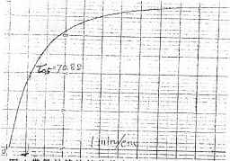
Fig. 4 The flying characteristic curve of a sheathed thermocouple with a protective tube
Strictly speaking, temperature-measured thermoelectric elements are not first-order, most of them are second-order or third-order or higher, and some have high-order characteristics due to poor heat transfer due to bad process. The transfer function is:
G(S)=K1/(T1S+1)•K2/(T2S+1)...Kn/(TnS+1)=K/(T1S+1) • (T2S+1)......(TnS+1 )......(15)
Due to the poor structure and process, these products cause a pure lag (Ï„) in the initial stage of the response and a large volume lag (Ï„c) in the later stage. The transfer function can be approximated as:
G(s)=e-τs•K/(TcS+1)......(16)
Its jump response curve is shown in Figure 5.
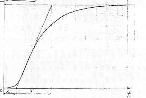
Fig. 5 Flying characteristic curve of temperature-recovered thermoelectric device with apparent hysteresis characteristics
Because the dynamic characteristics of temperature-measurement thermoelectric elements are too different, one of the parameters T, Ï„, and Tc cannot be used to express the response time simply and clearly. Therefore, in order to evaluate the dynamic characteristics of temperature-measured thermoelectric elements, international and national standards are adopted in the order. The response time of the thermoelectric element under the perturbation disturbance changes to 10%, 50%, and 90% of the perturbation value to measure its response speed, and is represented by Ï„0.1, Ï„0.5, Ï„0.9. This is more specific than using the T, Ï„, and Tc parameters. For convenience, Ï„ 0.5 is sometimes used to measure and compare the response temperature of thermoelectric elements.
2 measures to improve the dynamic characteristics of temperature thermoelectric elements
Over the years, due to the structural and technological reasons of many thermometric thermoelectric elements, especially high temperature and high pressure thermocouples with protective tubes, the slow response speed (Ï„0.5=90-120S) has greatly affected the process monitoring. The performance of the system makes the inertial system less responsive. Therefore, people have been looking for ways to improve the dynamic characteristics of thermoelectric thermoelectric elements. From the theoretical analysis, it can be known that the dynamic characteristics of temperature-measuring thermoelectric elements are good or bad, that is, the response speed of the temperature measurement process is determined by the inertial magnitude of each heat transfer section, that is, to improve their dynamic characteristics, the respective transmission must be reduced. The inertia time constant T of the hot link, which is determined by the product of the equivalent thermal resistance Ri of each heat transfer link and the heat capacity of the heat transfer target of each link, must be taken to improve it.
2.1 The following measures in manufacturing can reduce the time constant of each link.
2.1.1 Minimize the heat capacity of heat transfer targets at each stage Ci For example:
1) The end of the protective tube is made into a thin cylindrical body to reduce the end volume to reduce the heat capacity Ci; Figure 6 (a) and (b) are the larger diameter thermocouple (WRNK-15) The step response curve of a thermocouple (WRNK-17) with a smaller diameter tip can be seen from the figure.
2) The use of small-diameter armored thermoelectric elements can reduce the heat capacity C2 and C3; Table 1 shows the response speeds of several different diameter armored thermocouples that rapidly transfer from the freezing point to the boiling water bath. It can be seen from the table that small The response speed of a thermocouple of a diameter is indeed very fast.
Table 1 Comparison of response speeds of different diameters of armored thermocouples
3) Use of small-sized components (small diameter thermocouples and micro-film thermocouples (thermal resistance) can reduce the thermal capacity of assembled thermocouples (thermal resistance) C2 and the thermal capacity of buried, surface-type thermocouples (thermal resistance) C ;
2.1.2 Minimize the equivalent heat transfer resistance of each link
1) For the surface type and embedded type component manufacturing, the structure shape that enlarges the contact area between the component and the measured interface should be selected, and the insulating thickness and air gap should be minimized in order to reduce the thermal resistance R;
2) For assembly thermocouples and thermal resistances, the air gap should be minimized to achieve the purpose of reducing the equivalent thermal resistance R2;
3) Armored thermocouples and thermal resistors with protective tubes shall be provided with an increased contact area between the sleeve and the even-core element, such as spring-pressing the even-core element or dimensioning the inner bore of the protective tube to match that of the even-core element ( Cylindrical or conical contact (like WRNK-15 and WRNK-17 in Figure 6) and minimize the air gap to reduce R2.
4) The use of high-density insulating materials (compacting and compacting MgO or quartz powder) to manufacture the armored components can reduce the thermal resistance R. Figure 7 shows the same model used for compaction (a) and non-tamping (b). There are obvious differences in the flying characteristics of the two tile thermocouples of this process.
2.1.3 Reduce the number of links from the structure to increase the response speed of the components.
The reduction of the number of links is actually a reduction in order, and one or two links of multiple links can be eliminated at the time of design. For example, thermocouples and thermal resistors with protective tubes can be structurally modified to make small inertial thermocouples and thermal resistors in two ways:
1) The method of grounding the components (this method is limited to thermocouples) welds the hot junction of the thermocouple with the end of the protection tube and processes it into a thin elemental cylinder. This method actually has only one step left. The hot junction is integrated with the end of the protection tube, that is, only one heat capacity is left, and therefore, an extremely fast temperature measurement response speed is achieved. This type of thermocouple is only suitable for systems that allow hot junctions to be grounded, such as isolated dynamic tables, simple controllers that float in the system, etc. A fatal problem with thermocouples with grounded components is that the thermal components are grounded. This can cause two points of grounding in the general monitoring system. This increases the system disturbance significantly, causing the analog meter to float, causing the digital display to jump, especially for computer monitoring. System, component grounding sometimes makes the system simply can not work, and even cause I / O module damage, so this structure is rarely used.
2) Insulation of components
In this way, the end of the protective tube and the body of the armored element are combined to form a secondary composite full-sheathed thermocouple (thermal resistance) with a protective tube. Although this structure only reduces one heat transfer step ( T2 = 0). There are two links remaining. The characteristics are similar to armored thermocouples without a protective tube. However, due to the use of small components and very dense insulation, a very fast temperature response is achieved. Obtained a patent, people call it ultra-small inertia high temperature and high pressure armored thermocouple (hydrophobic probe). Fig. 8 is the step response curve of a thermocouple produced according to this guiding ideology. Its Ï„0.5 reached 3.24 seconds.
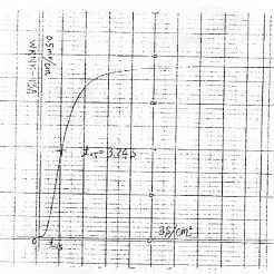
Figure 8 The soaring characteristics of hydrophobic control needles
2.2 Measures to be taken in use
2.2.1 Thermocouples and thermal resistors with low inertia should be selected as far as possible. If no thermocouples and thermal resistors are used, choose a fully-armored thermocouple and thermal resistance, and use a type with a thin pillar tip protection tube. If necessary, use an ultra-small inertial high-temperature high-pressure armored thermocouple and thermal resistance (hydrophobic probe ) This can guarantee the rapidity of the monitoring of the production process. Ensure the protection system's action is accurate and timely (such as steam turbine anti-water protection); greatly improve the temperature adjustment system's response speed, thereby improving the system's adjustment quality.
2.2.2 Measures for Installation
1) For surface type and embedded type components, the contact area and tightness of the component with the measured boundary should be increased as much as possible (if necessary, the collector should be installed and pressed); minimize the air gap (the gel may be injected if necessary or Silicon grease is filled to achieve the purpose of reducing thermal resistance;
2) Thermocouples and RTDs with protective tubes should be selected for areas where the flow velocity of the medium to be measured is fast (avoiding the flow dead area), such as facing the flow direction, etc. This can reduce the R1 of the thermocouples and thermistors with protective tubes.
2.2.3 Measures and precautions to be taken in use
1) Appropriately select the filter time constant of the AI ​​channel of the monitoring system so that it can meet the requirements of anti-jamming and meet the needs of rapidity of the channel;
2) The use of rapid temperature-measurement thermoelectric elements should re-revise the relevant setting values ​​of the protection system and the alarm system. If no modification is made, the sensitivity of the system can be improved; if it is modified, the probability of misoperation of the system can be reduced. For example, the rate determination of the automatic hydrophobic system based on the rate of change should be appropriately increased, and the value of the deviation of the alarm system determined based on the dynamic deviation should be appropriately increased.
3) The use of rapid temperature thermoelectric elements should be re-tuned to the dynamic parameters of the automatic adjustment system (such as integration time, etc.) in order to give full play to the characteristics of the system's rapid response.
3 implementation effect
In order to verify the conclusion of the above theoretical analysis, we have tested the dynamic characteristics of typical products of some domestic manufacturers, and Table 2 lists the measured values ​​of the response speeds of thermocouples with different structures and protective tubes. Table 3 is a comparison of the response speeds of the thermocouples of the sheathed tile of different processes. The test still uses a rapid transfer from an ice bottle to a boiling water bath.
Table 2 Comparison of response speeds of several thermocouples with protective tubes
Types of
model
Response speed (Ï„0.5) seconds
Manufacturer
General assembly type with protective tube
WRN—03
90---120
Domestic general factory
Armored with protective tube
WRNK-15
70.8
Shenyang Yuguang
Armored contact with protective tube
WRNK-15A
51
Shenyang Yuguang
Armored type with tip pillar protection tube
WRNK-17
twenty four
Shenyang Yuguang
Hydrophobic probe
WRNK-13A
3.24
Shenyang Yuguang
Table 3 Comparison of Response Speeds of Different Process Thermocouples
Types of
model
Response speed (Ï„0.5) seconds
Non-tamped armored thermocouples with insulating ends
WRNK-192φ4
6.51
End insulation material compacted armored thermocouple
WRNK-192φ4
1.00
From the data in the table, we can see that the test results are consistent with the theoretical analysis conclusions, and the improvement measures do have obvious effects.
Zhao Hanjie (Liaoning Electric Power Research Institute, Shenyang 110006)
Abstract : The dynamic characteristics of the temperature measurement process of thermoelectric thermoelements is determined by its own structure, processing technology and installation method. This paper proposes methods to improve the dynamic characteristics of thermoelectric elements for temperature measurement from aspects of design, manufacture and use. Professionals in the design, manufacturing, and use departments.
Keywords: temperature thermoelectric element dynamic characteristics improvement
Thermoelectric thermoelements used in production process monitoring and control include thermocouples and thermal resistors. The structure of the thermoelectric elements varies depending on the parameters and states of the measured medium and the mounting method. Temperature thermoelectric elements commonly used in power systems include thermocouples (thermal resistance) for measuring fluid medium temperature with protective tubes; surface-type thermocouples (thermoresistors) for measuring metal body temperature, pressure vessels, and pipelines; Thousands of thermocouples (thermal resistance) for rotary machine bearings, bearings, and thrust pads; embedded thermocouples (thermal resistance) for measuring the temperature of motor core coils and thermocouples (thermal resistance) for measuring air temperature. The thermoelectric elements, regardless of their structure or how the temperature measurement principle is different, change the temperature of the sensitive part with the temperature of the measured medium. Therefore, the temperature-measurement thermoelectric element must perform heat exchange with the measured medium during temperature measurement. The response speeds of temperature measurement thermoelectric elements with different structures and different uses have great differences due to the speed of heat exchange and the magnitude of thermal inertia. Therefore, it is necessary to carry out the dynamic characteristics of temperature measurement thermoelectric elements. Research to guide the component processing technology and structural improvement, guide the design of the monitoring system, component selection, sample installation and commissioning, to improve the reliability of the production process, economic, and improve product quality.
1 Temperature characteristics of thermoelectric elements:
1.1 Dynamic Characteristics of Thermocouples (Thermistors) Without Protection Tubes
Thermocouples without a protective tube (thermal resistance) are often used for surface temperature and buried temperature measurements, such as metal wall temperatures, bearing temperatures, motor core coil temperatures, etc., and are rarely used directly in other applications such as flowing media. When a thermocouple (thermal resistance) is used for temperature measurement, the temperature change of the thermocouple (eg, temperature rise) is due to the heat flowing between the measured medium (heat source) and the thermocouple element, which belongs to the heating (cooling) process of an object. . When the heat source temperature is θ1, the temperature θ2 of the object changes due to the change of θ1. Let X = θ1 and Y = θ2 be the model for heating (cooling) the object as shown in Fig. 1.
Q=λΔt•F/δ=λ(θ1-θ2)F/δ (1)
In the formula: Q, λ, δ, F, Δt, θ1, θ2 are heat flow (heat transferred per unit time), thermal conductivity, thickness of heat-conducting layer, heat-conducting area, temperature difference, and sensitive area of ​​measured medium and heat element. temperature. From formula (1), we can see that the thermal conductivity is proportional to the thermal conductivity, the thermal conductivity area and the temperature difference, and is inversely proportional to the thickness of the thermal layer. According to formula (1), people choose the insulating material with high thermal conductivity to manufacture the temperature measuring element and try to increase the temperature The contact area between the component and the measured medium, and the thickness of the insulating layer as much as possible to improve the response speed of the temperature measurement process.
Equation (1) is similar to the current conduction formula in the wire:
I=λU•S/I=λ(V1-V2) • S/I=gΔV=U/R...(2)
In the formula, I is the current, λ is the conductivity, U is the voltage, S is the cross-section of the wire, I is the length of the wire, and V1 and V2 are the potentials at both ends of the wire. (2) where λ•S/I is the conductance g of the wire, and its reciprocal is resistance R, which is an analogy. If we make λ•F/δ=gR in (1), gR is the thermal conductivity. , then 1/gR = RR is the thermal resistance during heat transfer. Therefore, (1) can be written as:
Q=λΔt•F/δ=gRΔt=Δt/RR...(3)
The actual heat transfer in the temperature measurement process is often not a simple heat conduction, for example, the components often come into point contact with the solid surface, the heat transfer layer often has an air gap, etc. Therefore, the temperature measurement process is always accompanied by heat radiation and convection. Exothermal.
In fact, most of thermoelectric thermoelements have the same three heat transfer methods during temperature measurement. Only the surface temperature measurement and buried temperature measurement process is based on heat conduction, while heat radiation and convection heat transfer Less; while in the process of fluid temperature measurement, there is more convection heat, and both thermal radiation and heat conduction exist.
In order to facilitate the study of the dynamic characteristics of the thermoelectric element for temperature measurement, we convert all three heat transfer methods to the heat conduction method and express the basic formula of heat transfer as follows:
Q=KFΔt...(4)
In the formula, k is the heat transfer coefficient, and F is the area of ​​the two heat exchange sections. The product of the two is the thermal conductivity gR in the formula (3), which is called the equivalent thermal conductivity. Let RR=1/gR be the pass Equivalent thermal resistance in thermal processes. Therefore, (4) can be written as:
Q=gRΔt=Δt/RR...(5)
This is the same as the expression of the current calculation formula in the conductor.
Assuming that the thermal capacity of the heat-sensitive area of ​​the device is CR, the temperature-rise characteristics of the device's heat-sensitive area during the temperature measurement process is the same as the charge and discharge process of the capacitor. When the input θ1 is a unit step function, the output will be Increase by exponential curve, ie:
Θ2=θ1(1-et/T)......(6)
Its flying characteristic curve is shown in Figure 2
It can be seen from Fig. 2 that the temperature measurement process of the surface type and embedded components belongs to the inertia link. In the figure, the time T is the time when the output θ2 rises to 0.632 times the stable output value K, which represents the time The magnitude of inertia, called the inertia time constant, is equal to the product of equivalent thermal resistance and heat capacity, ie T = RRCR. The transfer function of this link is:
G1(S) = K/(TS+1)......(7)
From Equation (7) and T=RRCR, it can be seen that the product of the equivalent thermal resistance of the component temperature measurement process and the thermal capacity (mass size) of the sensitive component of the component determines the response speed during temperature measurement.
1.2 Dynamic Characteristics of Armored Thermocouples (Thermistors)
The temperature measurement process (excluding axial heat transfer) of a general sheathed thermocouple (thermal resistance) without a protective tube can proceed from the measured medium to the end of the heating element body (stage 1) and from the end of the body. The element end (thermocouple hot junction or thermal resistance element) (link 2) is divided into two parts, and the dynamic characteristics of the two parts of the temperature measurement process are first order inertia links. Let G1(S) and G2(S) be the transfer functions of link 1 and link 2, respectively. K1 and K2 are the gains of the two links, and T1=R1C1 and T2=R2C2 are the inertia time constants of the two links, respectively. The dynamic mathematical models of the two links are:
G1(S) = K1/(T1S+1) (8) G2(S) = K2/(T2S+1) (9)
In the process, heat passes through the link 1 and link 2 to the sensitive area of ​​the thermal element in sequence from the measured medium, so the two links are in series. The transfer function G(S) of the whole process is the product of the two links transfer function, ie:
G(S)=G1(S)•G2(S)=K1•K2/(T1S+1)(T2S+1)=K/(T1S+1)(T2S+1)......(10)
Where K is the gain of the whole system, according to the output Y is the temperature, its value is 1°C/°C=1, and the output is calculated as the thermoelectric potential, and the value is according to the different thermocouple's index number according to each section of its thermoelectric value curve. Calculation, the dimension is mV/°C. From the formula (10), it can be seen that the temperature measurement process of a general sheathed thermocouple (thermal resistance) without a protective tube has a second-order inertial characteristic. However, because the outer diameter of the general sheathed thermocouple (thermal resistance) and the thermal element are small, and the insulating layer outside the thermal element is a dense MgO with high thermal conductivity, its T1 = R1C1 and T2 = R2C2 are both Very small, so armored thermocouples (thermal resistance) have a very fast dynamic response.
1.3 Dynamic Characteristics of Assembled Thermocouples (Thermistors)
The dynamic characteristics of an assembled thermocouple (thermal resistance) with a protective tube are similar to those of a general sheathed thermocouple (thermal resistance) without a protective tube, and can be measured from the medium to the end of the protective tube (stage 1). ) and from the end of the protective tube to the end of the thermal element (thermocouple hot junction or thermal resistance element) (link 2) is divided into two links, it is also a second-order inertial system. In the first step, heat conduction, convection and radiation exist at the same time. Since the protection tube has a large size (C1 is large), it has a large T1 value; the second part of the heat transfer medium is not MgO but mainly air. The gap has a large thermal resistance and therefore has a large T2 value; this results in a very slow dynamic response speed of the assembled thermocouple (thermal resistance). Figure 3 shows the fly-through characteristics of a preassembled thermocouple with a shroud pipe that rapidly transfers from an ice bath to a boiling water bath. It can be seen from the figure that the dynamic response speed of an assembled thermocouple is indeed very slow.
Fig. 3 Flying characteristic curve of an assembled thermocouple with protective tube
1.4 Dynamic characteristics of a full armored thermocouple (thermal resistance) with protective tube
The temperature measurement process (excluding axial heat transfer) of the full armored thermocouple (thermal resistance) with protective tube can be from the measured medium to the end of the protective tube (stage 1) and from the end of the protective tube to the end of the body (Section 2) and divided into three links from the end of the carcass to the sensitive area of ​​the thermal element (Link 3). The dynamic characteristics of the temperature measurement process of these three links are the first-order inertial system. Let G1(S), G2(S), and G3(S) be the transfer functions of link 1, link 2, and link 3, respectively. K1, K2, and K3 are the gains of the three links, respectively. T1 = R1C1, T2 = R2C2 And T3 = R3C3 are the inertia time constants of three links respectively, then the dynamic mathematics model of three links are:
G1(S)=K1/(T1S+1)......(11)G2(S)=K2/(T2S+1)......(12)G3(S)=K3/(T3S+1)......(13 )
In the heat transfer process, there are three kinds of heat transfer methods in the link 1, but the convection heat transfer component is larger; the link 2 is mainly based on conduction and radiation; and the link 3 is mainly heat transfer method, where T1, T2 T3, respectively, are the three inertial time constants, which are determined by the product of the respective heat transfer resistance and the heat capacity of the respective heat transfer target object.
The overall mathematical model of the temperature measurement process of a sheathed thermocouple (thermal resistance) with protective tube is: G(S) = K1/(T1S+1)•K2/(T2S+1)•K3/(T3S+1)= K/(T1S+1)•(T2S+1)•(T3S+1)......(14)
Visible, it is a third-order link. Although the temperature measurement system belongs to the third-order inertial system, due to the use of armored components and the fistula tube and the protection tube can be in direct contact, the R2 and R3 values ​​are smaller, and therefore a significantly faster response speed than the assembled thermocouple is obtained. . The flying characteristics of its step disturbance are shown in Fig. 4.
Fig. 4 The flying characteristic curve of a sheathed thermocouple with a protective tube
Strictly speaking, temperature-measured thermoelectric elements are not first-order, most of them are second-order or third-order or higher, and some have high-order characteristics due to poor heat transfer due to bad process. The transfer function is:
G(S)=K1/(T1S+1)•K2/(T2S+1)...Kn/(TnS+1)=K/(T1S+1) • (T2S+1)......(TnS+1 )......(15)
Due to the poor structure and process, these products cause a pure lag (Ï„) in the initial stage of the response and a large volume lag (Ï„c) in the later stage. The transfer function can be approximated as:
G(s)=e-τs•K/(TcS+1)......(16)
Its jump response curve is shown in Figure 5.
Fig. 5 Flying characteristic curve of temperature-recovered thermoelectric device with apparent hysteresis characteristics
Because the dynamic characteristics of temperature-measurement thermoelectric elements are too different, one of the parameters T, Ï„, and Tc cannot be used to express the response time simply and clearly. Therefore, in order to evaluate the dynamic characteristics of temperature-measured thermoelectric elements, international and national standards are adopted in the order. The response time of the thermoelectric element under the perturbation disturbance changes to 10%, 50%, and 90% of the perturbation value to measure its response speed, and is represented by Ï„0.1, Ï„0.5, Ï„0.9. This is more specific than using the T, Ï„, and Tc parameters. For convenience, Ï„ 0.5 is sometimes used to measure and compare the response temperature of thermoelectric elements.
2 measures to improve the dynamic characteristics of temperature thermoelectric elements
Over the years, due to the structural and technological reasons of many thermometric thermoelectric elements, especially high temperature and high pressure thermocouples with protective tubes, the slow response speed (Ï„0.5=90-120S) has greatly affected the process monitoring. The performance of the system makes the inertial system less responsive. Therefore, people have been looking for ways to improve the dynamic characteristics of thermoelectric thermoelectric elements. From the theoretical analysis, it can be known that the dynamic characteristics of temperature-measuring thermoelectric elements are good or bad, that is, the response speed of the temperature measurement process is determined by the inertial magnitude of each heat transfer section, that is, to improve their dynamic characteristics, the respective transmission must be reduced. The inertia time constant T of the hot link, which is determined by the product of the equivalent thermal resistance Ri of each heat transfer link and the heat capacity of the heat transfer target of each link, must be taken to improve it.
2.1 The following measures in manufacturing can reduce the time constant of each link.
2.1.1 Minimize the heat capacity of heat transfer targets at each stage Ci For example:
1) The end of the protective tube is made into a thin cylindrical body to reduce the end volume to reduce the heat capacity Ci; Figure 6 (a) and (b) are the larger diameter thermocouple (WRNK-15) The step response curve of a thermocouple (WRNK-17) with a smaller diameter tip can be seen from the figure.
2) The use of small-diameter armored thermoelectric elements can reduce the heat capacity C2 and C3; Table 1 shows the response speeds of several different diameter armored thermocouples that rapidly transfer from the freezing point to the boiling water bath. It can be seen from the table that small The response speed of a thermocouple of a diameter is indeed very fast.
Table 1 Comparison of response speeds of different diameters of armored thermocouples
3) Use of small-sized components (small diameter thermocouples and micro-film thermocouples (thermal resistance) can reduce the thermal capacity of assembled thermocouples (thermal resistance) C2 and the thermal capacity of buried, surface-type thermocouples (thermal resistance) C ;
2.1.2 Minimize the equivalent heat transfer resistance of each link
1) For the surface type and embedded type component manufacturing, the structure shape that enlarges the contact area between the component and the measured interface should be selected, and the insulating thickness and air gap should be minimized in order to reduce the thermal resistance R;
2) For assembly thermocouples and thermal resistances, the air gap should be minimized to achieve the purpose of reducing the equivalent thermal resistance R2;
3) Armored thermocouples and thermal resistors with protective tubes shall be provided with an increased contact area between the sleeve and the even-core element, such as spring-pressing the even-core element or dimensioning the inner bore of the protective tube to match that of the even-core element ( Cylindrical or conical contact (like WRNK-15 and WRNK-17 in Figure 6) and minimize the air gap to reduce R2.
4) The use of high-density insulating materials (compacting and compacting MgO or quartz powder) to manufacture the armored components can reduce the thermal resistance R. Figure 7 shows the same model used for compaction (a) and non-tamping (b). There are obvious differences in the flying characteristics of the two tile thermocouples of this process.
2.1.3 Reduce the number of links from the structure to increase the response speed of the components.
The reduction of the number of links is actually a reduction in order, and one or two links of multiple links can be eliminated at the time of design. For example, thermocouples and thermal resistors with protective tubes can be structurally modified to make small inertial thermocouples and thermal resistors in two ways:
1) The method of grounding the components (this method is limited to thermocouples) welds the hot junction of the thermocouple with the end of the protection tube and processes it into a thin elemental cylinder. This method actually has only one step left. The hot junction is integrated with the end of the protection tube, that is, only one heat capacity is left, and therefore, an extremely fast temperature measurement response speed is achieved. This type of thermocouple is only suitable for systems that allow hot junctions to be grounded, such as isolated dynamic tables, simple controllers that float in the system, etc. A fatal problem with thermocouples with grounded components is that the thermal components are grounded. This can cause two points of grounding in the general monitoring system. This increases the system disturbance significantly, causing the analog meter to float, causing the digital display to jump, especially for computer monitoring. System, component grounding sometimes makes the system simply can not work, and even cause I / O module damage, so this structure is rarely used.
2) Insulation of components
In this way, the end of the protective tube and the body of the armored element are combined to form a secondary composite full-sheathed thermocouple (thermal resistance) with a protective tube. Although this structure only reduces one heat transfer step ( T2 = 0). There are two links remaining. The characteristics are similar to armored thermocouples without a protective tube. However, due to the use of small components and very dense insulation, a very fast temperature response is achieved. Obtained a patent, people call it ultra-small inertia high temperature and high pressure armored thermocouple (hydrophobic probe). Fig. 8 is the step response curve of a thermocouple produced according to this guiding ideology. Its Ï„0.5 reached 3.24 seconds.
Figure 8 The soaring characteristics of hydrophobic control needles
2.2 Measures to be taken in use
2.2.1 Thermocouples and thermal resistors with low inertia should be selected as far as possible. If no thermocouples and thermal resistors are used, choose a fully-armored thermocouple and thermal resistance, and use a type with a thin pillar tip protection tube. If necessary, use an ultra-small inertial high-temperature high-pressure armored thermocouple and thermal resistance (hydrophobic probe ) This can guarantee the rapidity of the monitoring of the production process. Ensure the protection system's action is accurate and timely (such as steam turbine anti-water protection); greatly improve the temperature adjustment system's response speed, thereby improving the system's adjustment quality.
2.2.2 Measures for Installation
1) For surface type and embedded type components, the contact area and tightness of the component with the measured boundary should be increased as much as possible (if necessary, the collector should be installed and pressed); minimize the air gap (the gel may be injected if necessary or Silicon grease is filled to achieve the purpose of reducing thermal resistance;
2) Thermocouples and RTDs with protective tubes should be selected for areas where the flow velocity of the medium to be measured is fast (avoiding the flow dead area), such as facing the flow direction, etc. This can reduce the R1 of the thermocouples and thermistors with protective tubes.
2.2.3 Measures and precautions to be taken in use
1) Appropriately select the filter time constant of the AI ​​channel of the monitoring system so that it can meet the requirements of anti-jamming and meet the needs of rapidity of the channel;
2) The use of rapid temperature-measurement thermoelectric elements should re-revise the relevant setting values ​​of the protection system and the alarm system. If no modification is made, the sensitivity of the system can be improved; if it is modified, the probability of misoperation of the system can be reduced. For example, the rate determination of the automatic hydrophobic system based on the rate of change should be appropriately increased, and the value of the deviation of the alarm system determined based on the dynamic deviation should be appropriately increased.
3) The use of rapid temperature thermoelectric elements should be re-tuned to the dynamic parameters of the automatic adjustment system (such as integration time, etc.) in order to give full play to the characteristics of the system's rapid response.
3 implementation effect
In order to verify the conclusion of the above theoretical analysis, we have tested the dynamic characteristics of typical products of some domestic manufacturers, and Table 2 lists the measured values ​​of the response speeds of thermocouples with different structures and protective tubes. Table 3 is a comparison of the response speeds of the thermocouples of the sheathed tile of different processes. The test still uses a rapid transfer from an ice bottle to a boiling water bath.
Table 2 Comparison of response speeds of several thermocouples with protective tubes
Types of
model
Response speed (Ï„0.5) seconds
Manufacturer
General assembly type with protective tube
WRN—03
90---120
Domestic general factory
Armored with protective tube
WRNK-15
70.8
Shenyang Yuguang
Armored contact with protective tube
WRNK-15A
51
Shenyang Yuguang
Armored type with tip pillar protection tube
WRNK-17
twenty four
Shenyang Yuguang
Hydrophobic probe
WRNK-13A
3.24
Shenyang Yuguang
Table 3 Comparison of Response Speeds of Different Process Thermocouples
Types of
model
Response speed (Ï„0.5) seconds
Non-tamped armored thermocouples with insulating ends
WRNK-192φ4
6.51
End insulation material compacted armored thermocouple
WRNK-192φ4
1.00
From the data in the table, we can see that the test results are consistent with the theoretical analysis conclusions, and the improvement measures do have obvious effects.
Metal Bearings ,White Metal Bearing,Metal Ball Bearings,Precision Steel Balls
Ningbo Metal Sharing Supply Chain Management Co., Ltd , https://www.metalsharing.com